
Part 4 - Assembling the internals
- Prepare and tune the stabilizers needed for your preferred layout, if not done already.
Prepare and lube the switches as well. - Mount the stabilizers onto the PCB using the provided shims to fill the gap on the thin PCB.
The side with the copper artwork (logo) should face away from the PCB.
An example of shim use is shown below; the shim goes on the bottomside of the PCB, with the hook of the stabilizer hooking both the shim and the PCB.
Note: The pictured shim is an earlier revision; however, its usage remains the same.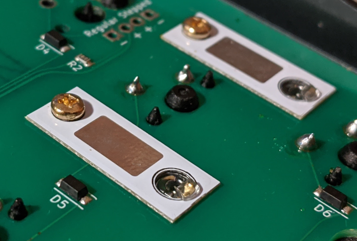
- If you plan to use the foam midlayer, install it above the PCB at this stage.
Our personal recommendation is to install it if you prefer a calmer/more muted sound. For the opposite, it is recommended to leave it out.
If using the midlayer, there is also an optional adhesive below-spacebar foam used to fill the gap below the spacebar. When installing this, align the foam to the case screw cutout and switch cutouts.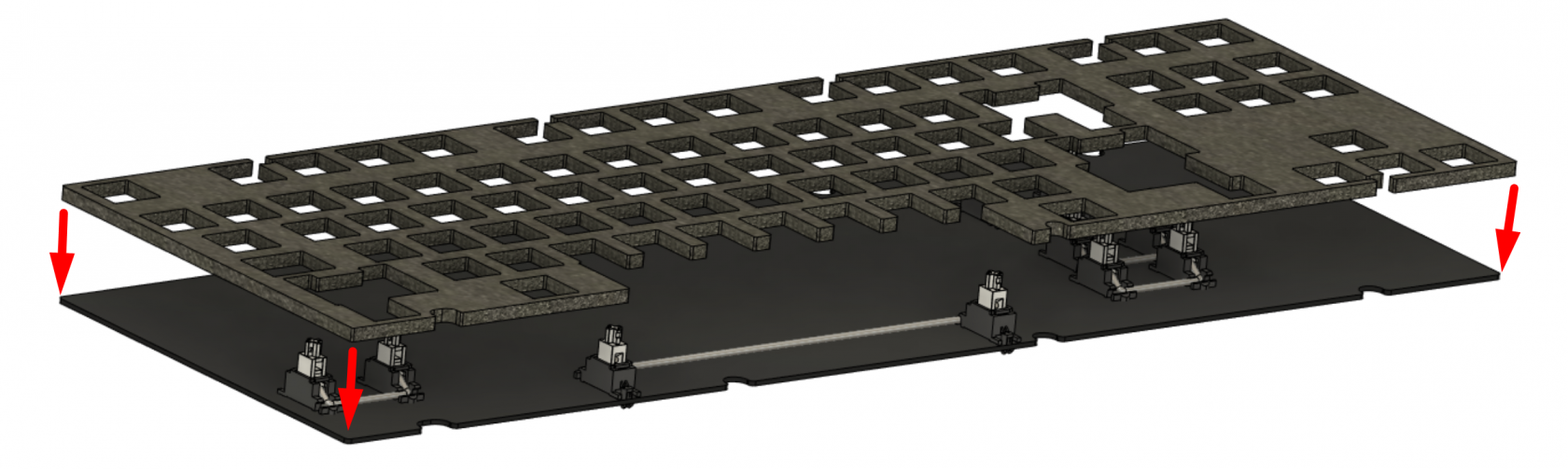
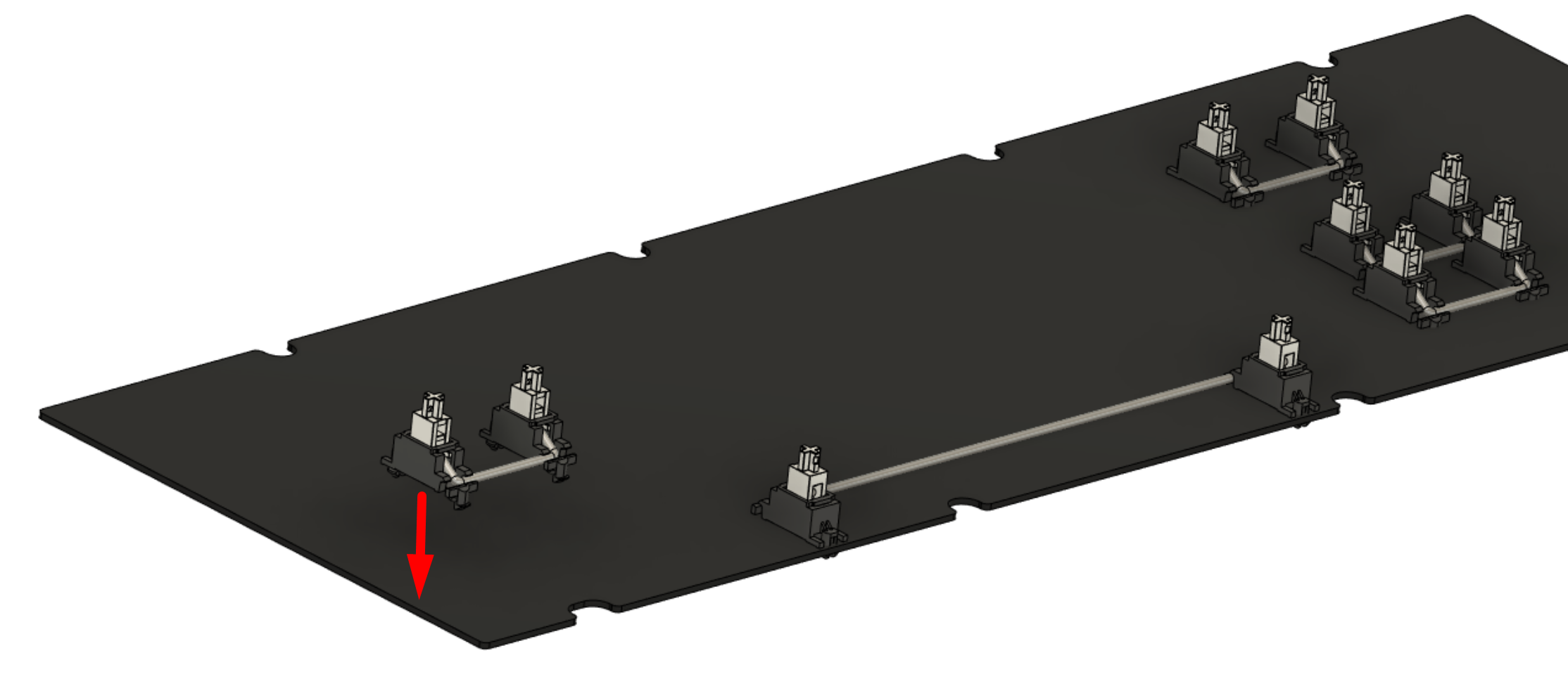
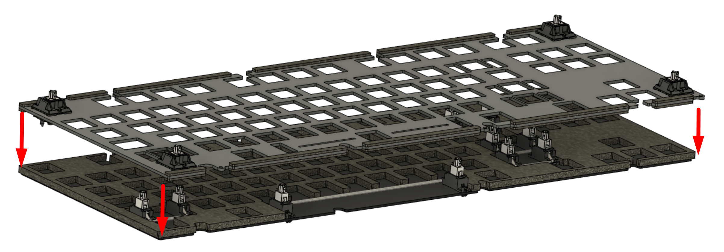
- Install the corner switches onto the plate for alignment, then install the plate onto the PCB.

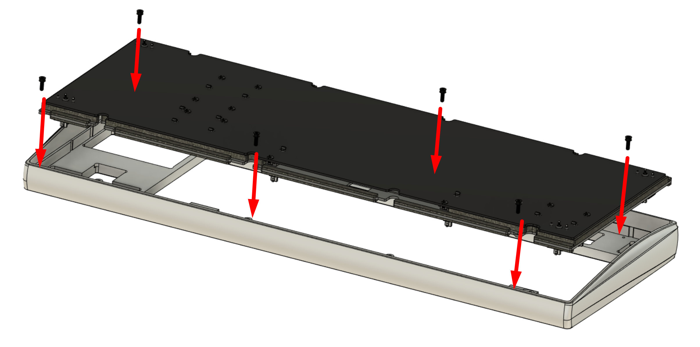
- Flip this assembly upside-down, and lower it into the case top half.
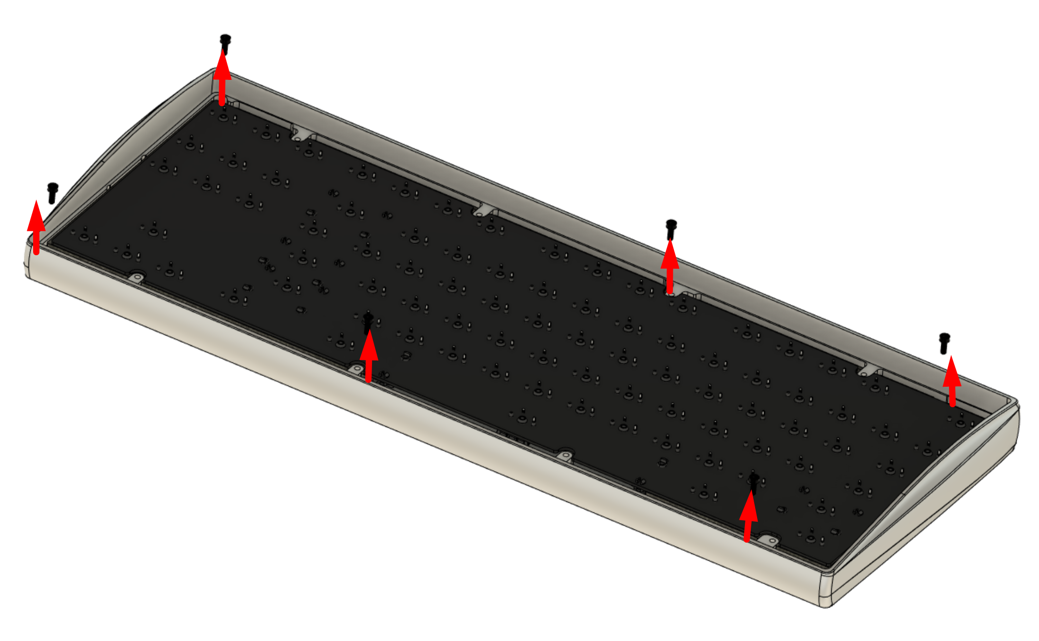
Secure the plate against the top using the temporary plate retention screws.
- Flip the assembly right-side up.
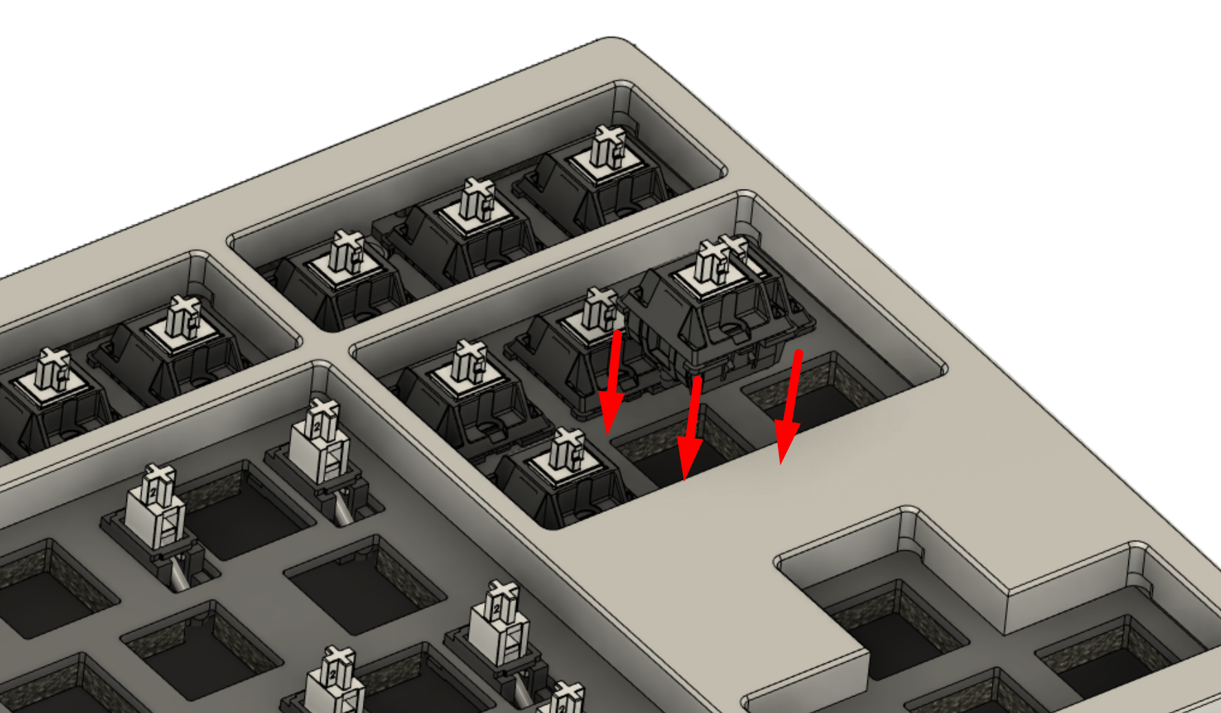
Install the rest of the switches carefully in the following process:- Double-check that the solder leads of the switches are straight; if they are not, bend them back into position.
- Fit the switch into the plate, and verify that the switch legs have successfully gone through the solder pads on the PCB.
- Double-check that the switch has fully clipped into the plate, and is making maximum contact with the PCB rather than floating.
- Once all the switches are fitted and confirmed both clipped in and making firm contact against the PCB, solder each switch leg into place.
Note: Having the PCB not fully secured against the switches can have detrimental effects for acoustics and typing feel. - Once the soldering is complete, remove the temporary plate retention screws.
At the end of the steps, you should have a completed assembly of the top case half, switches, stabilizers, plate, and PCB joined together.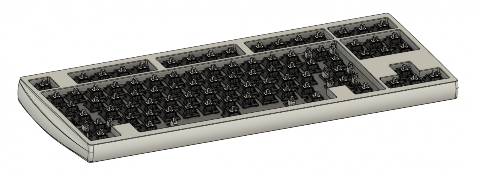
- In the same manner as done with the out-of-box testing, temporarily connect the daughterboard and its cable into the main PCB and plug it into a computer.
Use a key tester tool to verify that both the PCB functions properly and each key is successfully soldered.


The structure is now ready for final installation. Disconnect the daughterboard cable on the main PCB side.