
Part 3 - Preparing the case
Let's begin with the case.
- Unbox the keyboard and all related parts if not already done.
- Of the two supplied hex keys, use the larger one to unscrew the four weight screws.
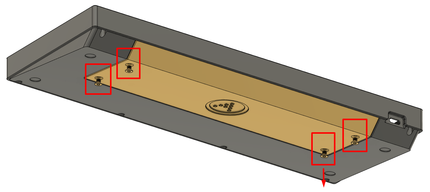
- Carefully remove the weight, and set aside.
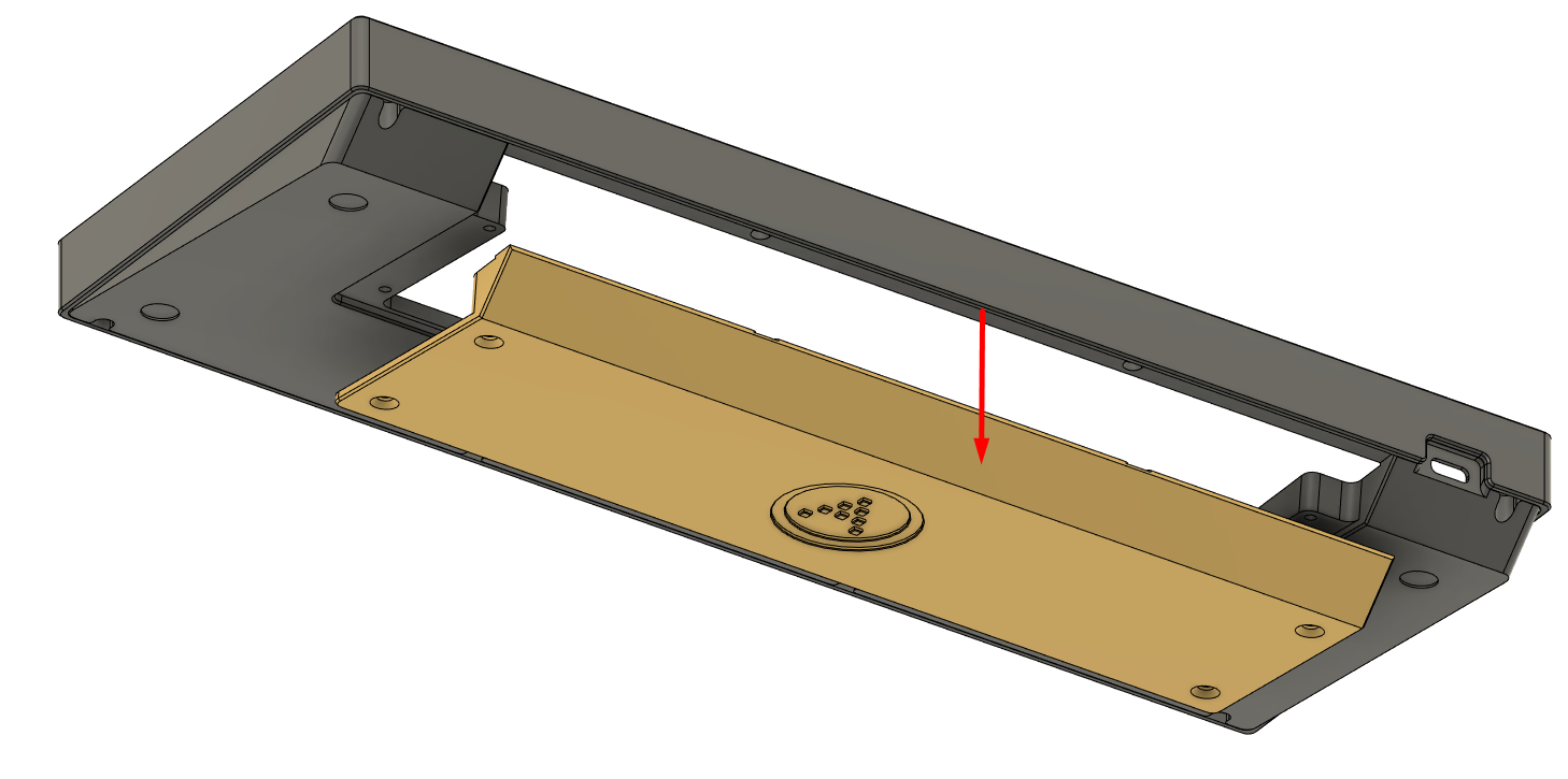
- Use the smaller of the two hex keys to unscrew the eight case screws.
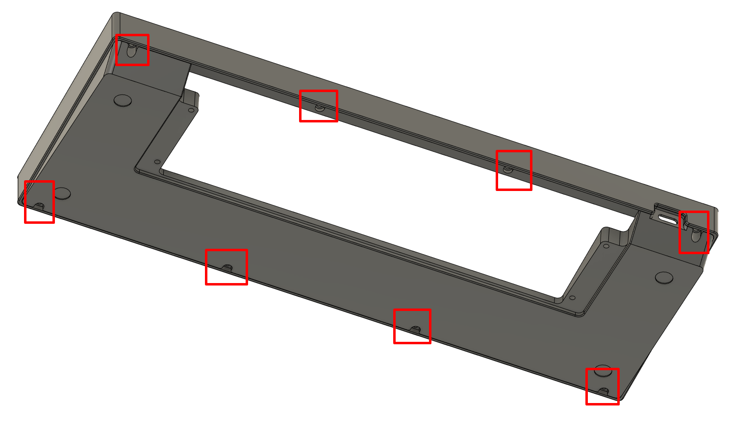
- Carefully remove the bottom case half, and set aside.
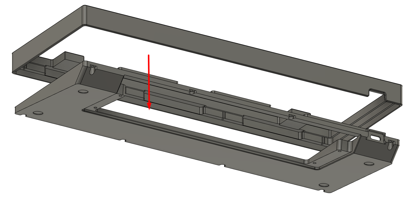
- At this point, the case should be fully disassembled.
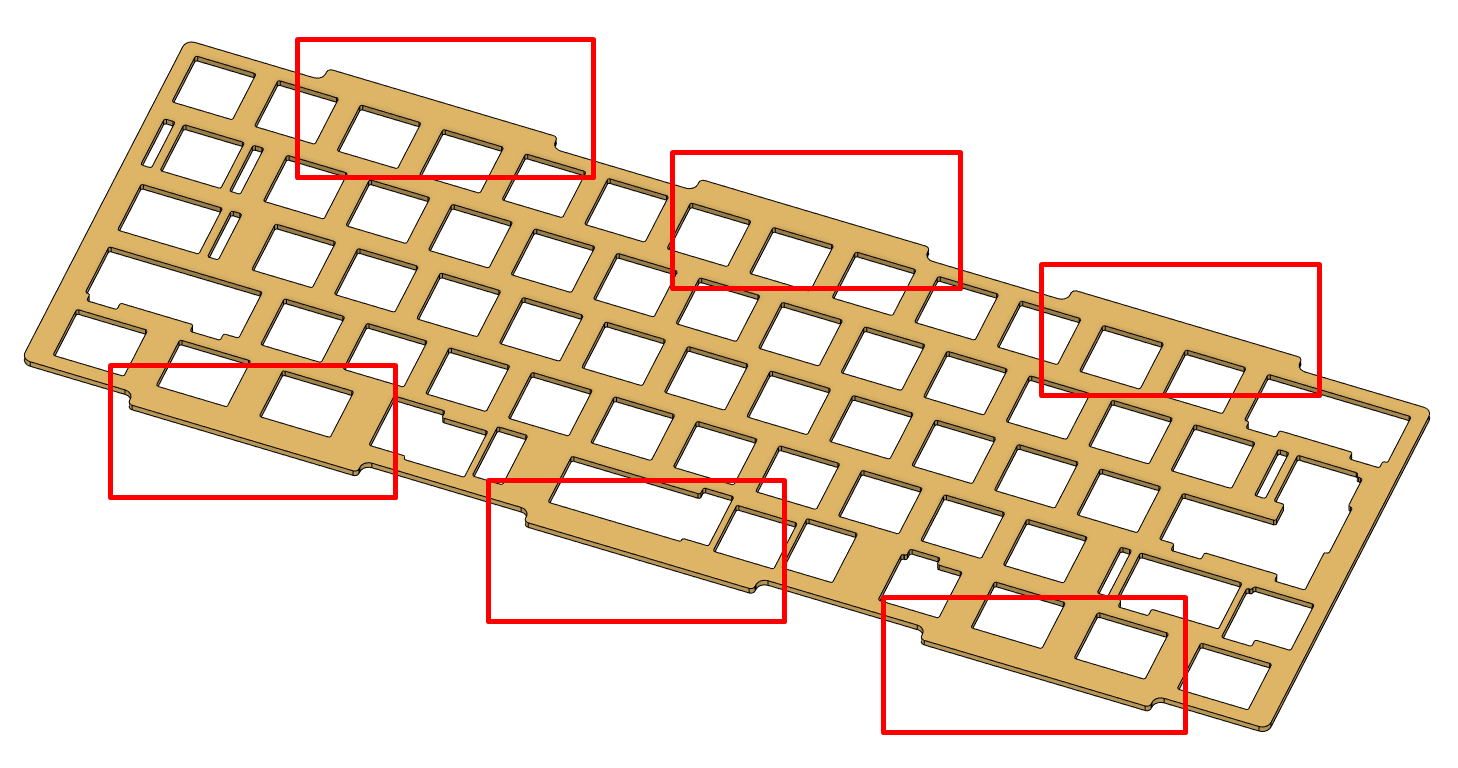
Prepare the plate and adhesive gaskets.
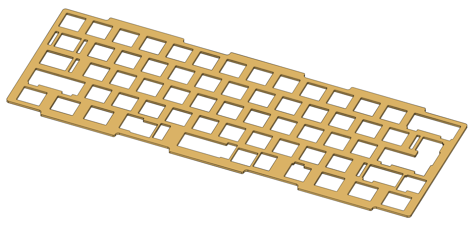
- Carefully place 6 of the long gaskets onto the plate, one per tab.
Note: For the minority who are planning on using aftermarket custom plates, install these gaskets on the case top area where the plate tabs overlap. For specific warnings and instructions, see here.

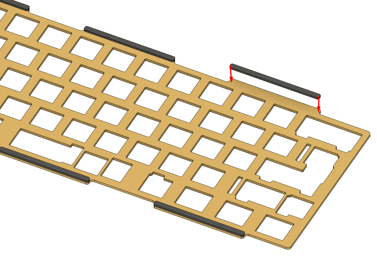
- Repeat on the underside; there should be 12 gaskets installed at the end of this step.
Note: As per the previous step, if you are planning on using aftermarket custom plates, place the gaskets on the bottom case half where the plate tabs overlap.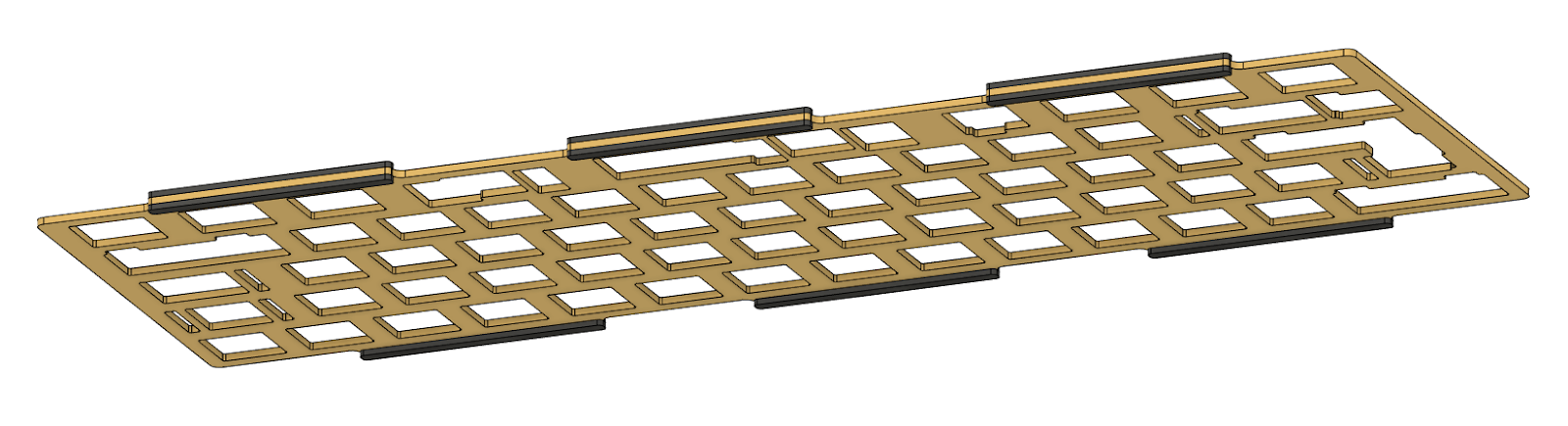
- Set the completed plate aside.
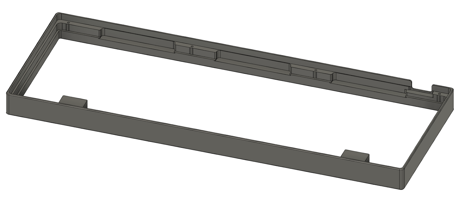
Prepare the case top half and the small rectangular gaskets.
- Place the small gaskets horizontally at roughly the points indicated, on the inner wall of the case.
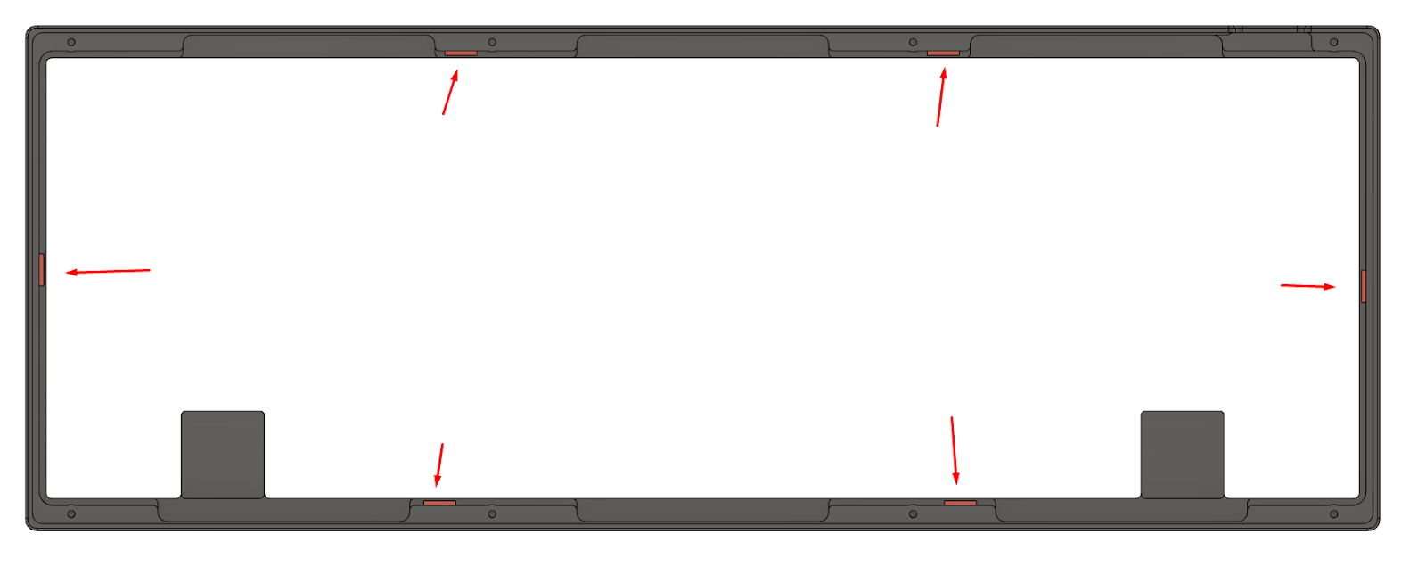
They should be placed at “plate-height” on the center band, flush to the lower edge as shown.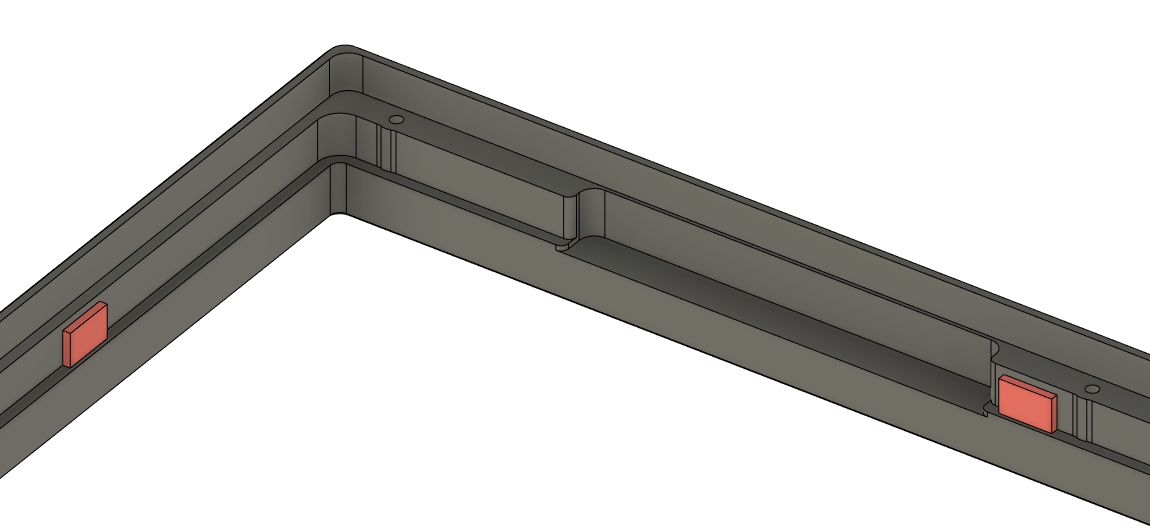
- Set the completed top case half aside.Prepare the case bottom half.
Install the provided rubber feet into the insets.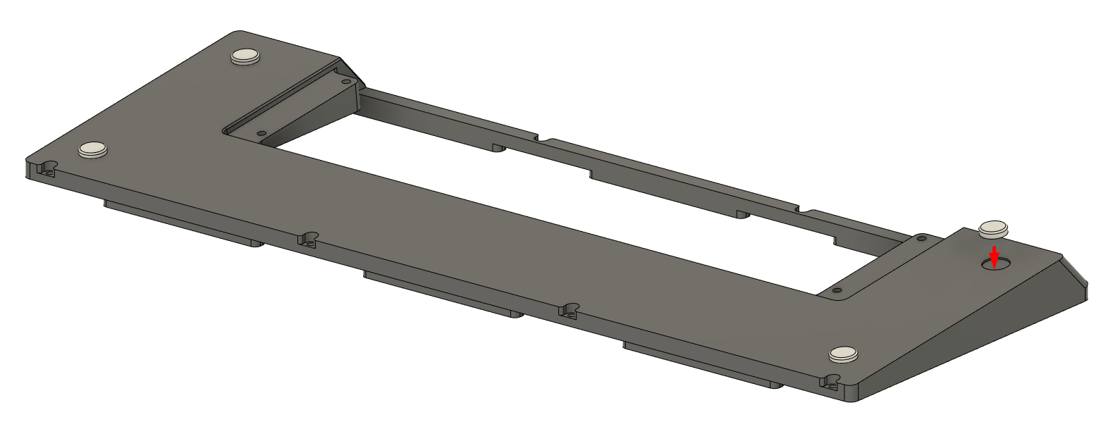
The case is now ready for assembly.


Now it is time to solder the switches.